The glow wire tester is designed according to IEC60695-2-10, UL746 and GB/T5169.10.
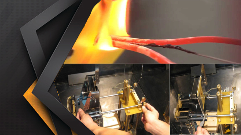
The specific material and sharp heating wire is heated to specific temperature
(550 ℃~960 ℃) for 1 min by max current, then vertical burns the EUT with certain pressure (1.0N) for 30s, then check if the test specimen and bedding material are burning, and count the burning time to judge the dangerousness of the specimen.
Generally it is applied to test flammability, GWIT and GWFI of lighting lamps, electronic products and household appliances The equipment is applicable to flame resistance test of all levels of QC departments and corresponding enterprises.
| Technical Specifications | |
| Glow wire temperature | 50~1000℃±2℃ |
| Glow time | 0-999.9s±0.1s (auto record) |
| Burning time | 0-999.9s±0.1s (auto record) |
| Flame Chilling time | 0-999.9s±0.1s (auto record) |
| Thermocouple | Φ0.5mm, K type |
| Glow wire | Φ4mm nichrome wire |
| Pressure on test specimen | 1N±0.2N |
| Depth | 7mm±0.5mm |
| Test speed | 14mm/s |
| Power Supply | AC220V/50Hz 500W |
| Dimension | W1100mm * D700mm * H1300mm |
Feature
GW-04 automated Glow-wire tester constructed in accordance with the International Electrotechnical Commission (IEC) 60695-2-10 2013 Fire hazard testing
– Part 2-10: Glowing/hot-wire based test methods – Glow-wire apparatus and common test procedure IEC60695-2-1 ,IEC60695-2-10~IEC60695-2-13 (GB/T5169.10-2006~GB / T5169.13-2006) and UL746A,IEC829, DIN695,VDE0471,
The glow-wire is kept in a horizontal plane;
Microprocessor corrects all changes in heating current so that it remains stable during the test;
Burning or glowing particles falling from the test specimen are able to fall without obstruction onto a specified layer to minimize the possibility of the spread of fire (this layer is a single layer of wrapping tissue resting on, and in close contact with the upper surface of a wooden board);
GW-04 have a wooden board (flat and smooth and having a minimum thickness of 10 mm) that can be positioned at a distance of 200 mm ± 5 mm below the place where the glow-wire is applied to the test specimen;
Supplied with wrapping tissue (as specified in ISO 4046-4:2002 Clause 4.215) with a mass per unit area of between 12 g/m2 and 30 g/m2 ;
The glow-wire shall be serviceable and constructed of Nickel/Chromium (> 77% Ni/20
± 1% Cr) wire; having an overall diameter of 4,00 mm +/-0.07 mm (before bending); Supplied with silver foil for calibration of the temperature measuring system
Stabilized voltage source (+/- 2% RMS). The test circuit shall contain a current measuring device which indicates a true RMS value with a maximum error of 1.0%;
Timing device with a resolution of 0.2 s or less;
Motor driven with a rate of approach and withdrawal 10mm/s ≤ v ≤ 25mm/s and a controlled application force of 0.95 N +/- 0.10 N for a duration of 30 s ± 1 s. This force
shall be applied and maintained at this value when the glow-wire or the test specimen is automatically moved horizontally one towards the other during testing;
The tip of the glow-wire into and through the test specimen shall be limited to 7mm ± 0.5 mm
All electrical connections capable of carrying the current without affecting the performance or long-term stability of the circuit;
The electrical connections of the GW-04shall provide a sufficient contact area (60 mm2 for glow-wire to stud connections at each end); and be properly secured (screwed, soldered, or brazed) between the glow-wire and stud connections.
Thermocouple wires suitable for continuous operation at temperatures up to 960°C;
A glow-wire tip that can be heated and stabilized to the following temperatures:
| Test Temperatures °C | Tolerances °C |
| 550°C | ± 10°C |
| 600°C | ± 10°C |
| 650°C | ± 10°C |
| 700°C | ± 10°C |
| 750°C | ± 10°C |
| 800°C | ± 15°C |
| 850°C | ± 15°C |
| 900°C | ± 15°C |
| 960°C | ± 15°C |
Scales for the depth of penetration and flame height reading with zero point adjustments;
Constructed of material that will protect against overheating, short circuit and break off in the circuit
Remote control for the operation outside the Stainless Steel Test Chamber
Supplied with an ISO/IEC 17025 certificate of calibration Calibrated by CVC (Vkan Certification &Testing Co., Ltd)
http://eng.cvc.org.cn/index.html
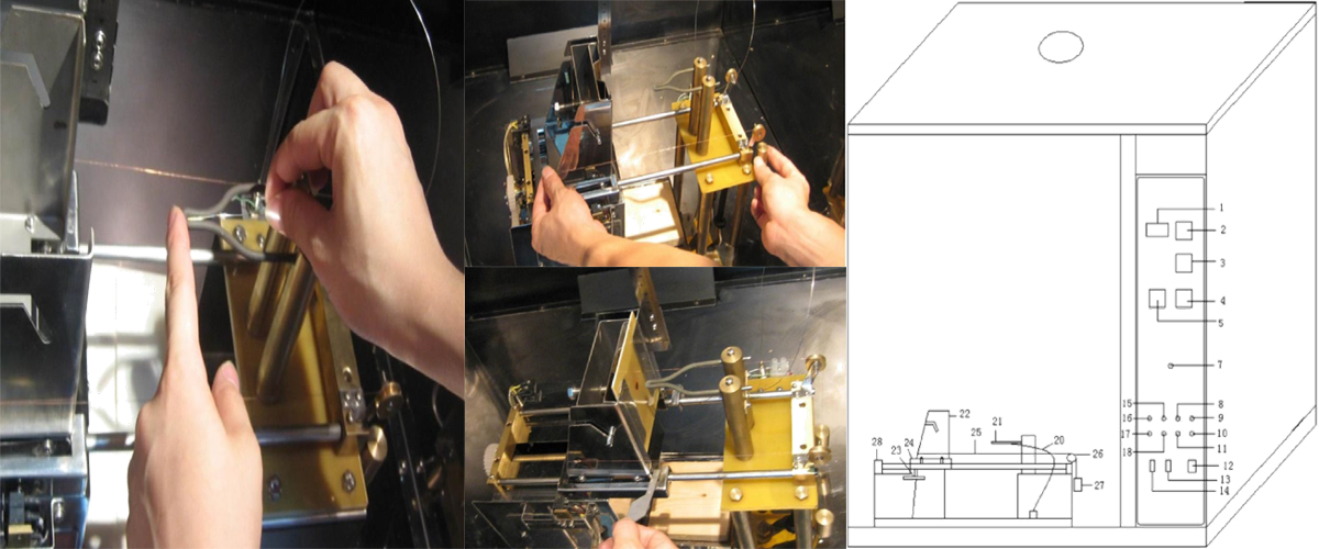
1. Electric current—indicate the glow-wire’s heating current
2. Heating timer—indicate and set the application duration that the tip of glow wire is applied to test specimen (Ta)
3. Ignition timer—indicate ignition duration (Ti)
4. Flame extinguish timer—indicate flame extinguish duration (Te)
5. Temperature controller—indicate and set up heating temperature with 1000 ℃ temperature protecting
6. Empty
7. Heating current regulation—set up current in a specific temperature
8. Heating start switch--- power supply to heat glow-wire
9. Ti stop—stop ignition timer
10. Te stop—stop extinguishing timer
11. Heating stop—cut off power supply of glow-wire
12. Power supply switch
13. Light switch
14. Fan switch—control vent-pipe
15. Left run —test specimen carriage go left when debugging
16. Test start—start to test
17. Test stop---stop the test and everything reposition
18. Right run—test specimen carriage go right
19. Empty
20. Thermocouple—measure temperature of glow wire
21. The tip of glow wire
22. Test specimen carriage
23. Limit control—adjust 7mm limits and start timer
24. Drive engine
25. Tinsel—pull the hammer
26. Low-friction rollers—bear the tinsel
27. Hammer—keep it in 1 newton force
28. Carriage reposition limit
1200
999
500
![]()
© 2022-2025- R.V Industries. All Rights Reserved | Design / Hosted by SIS